In assisting with a Kids Engineering class with a friend, Paul Lane, we evaluated a few platforms for kids to learn on. One platform stood out for teaching hardware control.
The Micro:bit is a complete platform of hardware and software that allows beginner to expert firmware development.
Hardware
The hardware schematics may be found here with a reference design here, and includes the following
- nRF51822-QFAA – Main application processor running at 16MHz (1.8v to 3.6V)
- 256kB Flash, 16kB RAM
- 2.4Ghz radio for Bluetooth Low Energy and custom protocols
- 10Bit ADC, I2C, SPI, UART
- MKL26Z128VFM4 – Auxiliary processor
- USB On-The-Go programmer for main processor (and serial interface pass-thru)
- Voltage Regulator (USB 4.5-5.25V to 3.3V), not used if batteries connected
- 128kB Flash, 16kB RAM
- 16 bit ADC, 12 bit DAC, I2C, SPI, UART, USB
- MMA8653FC – 3 axis accelerometer
- I2C selectable ranges of 10bit ±2g, ±4g, ±8g at 1.5 to 800Hz
- MAG3110 – 10 Gauss (±1000uT) Three-Axis, Digital Magnetometer
- I2C interface with 16bit data up to 80Hz
- Connectivity
- Bluetooth LE
- USB micro connector
- JST battery connector (up to 3.6V) – Be wary of 3.7V LiPo single cells. The nRF chip will handle up to 3.9V, but its reliability may be affected.
- 3 push buttons; 1 reset and 2 user programmable buttons
- Display (5×5 array of LEDs)
- 20 pin card edge connector (note that the holes accept 4mm banana terminals)

Hardware Overview
Software

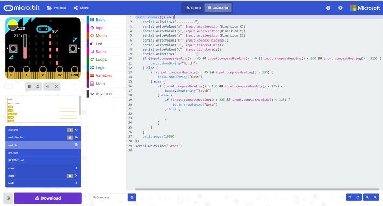
Enabling hardware usability is where the Micro:bit excelled. It intuitively bridges from Scratch-like visual programming to Arduino C-like text programming. It does this while giving access to the built-in sensors (magnetometer, accelerometer, luxmeter, capacitve touch, buttons, and raw ADC), LED matrix and extension-enabling communication buses (UART, I2C, SPI).
It may be programmed using different language options on most devices using USB (IOS and Android included via its Bluetooth interface).
Simulation
